
Free AI summary of this YouTube video by SumTube
Physics Project for Class 12 | Electromagnetic Induction Working Model | Physics Working Model
TL;DR
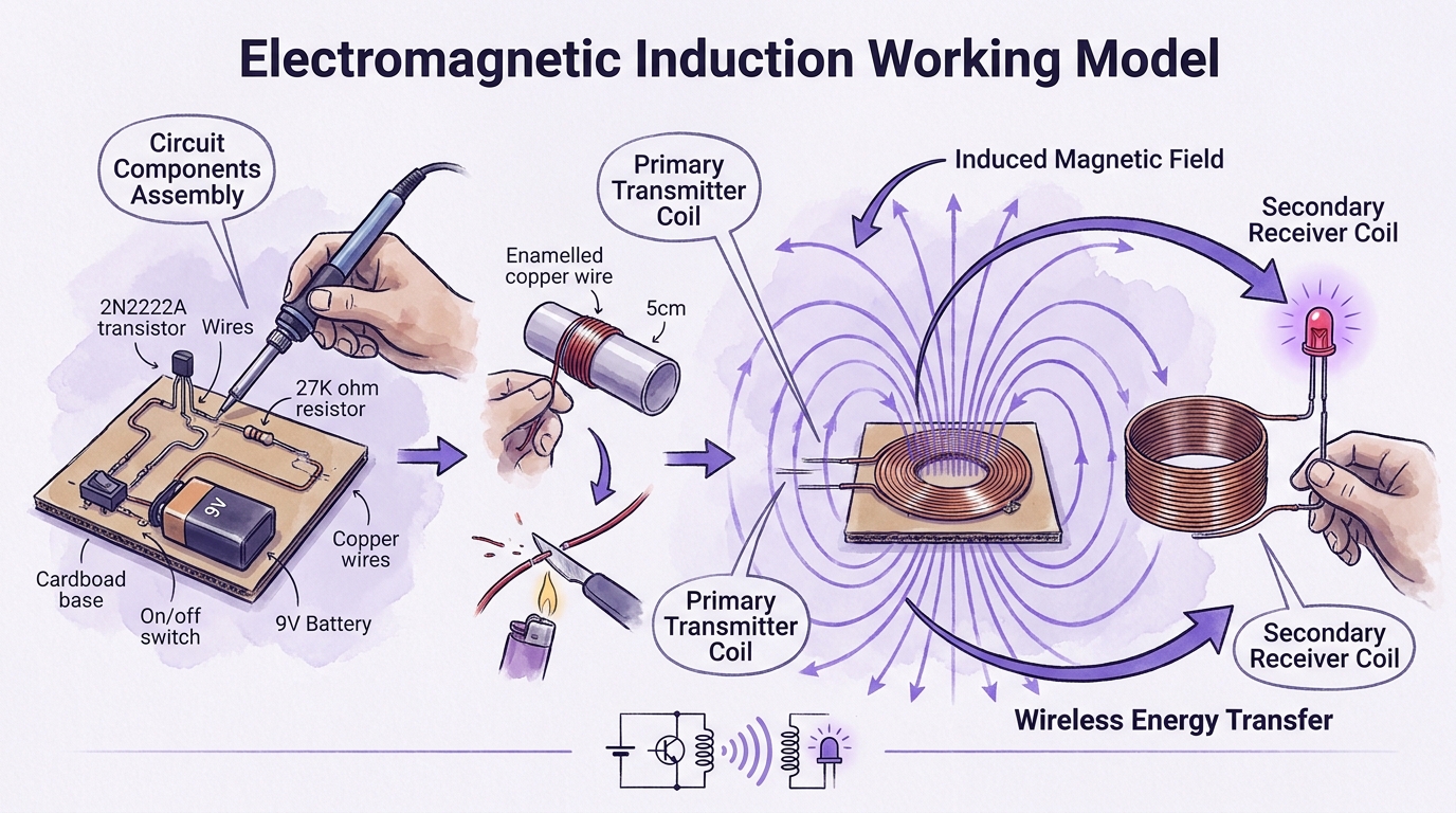
This video provides a step-by-step guide to constructing an electromagnetic induction working model for science projects or practical exams. It demonstrates how to assemble the required electronic components and copper wire coils to wirelessly illuminate an LED using an induced electromagnetic field. The creator also explains the underlying scientific principle and offers pre-made kits for purchase online.

Key takeaways
- 7:28Wireless energy transmission can be achieved using a 2N2222A transistor, a 27K ohm resistor, and copper coils to generate an alternating magnetic field
- 8:21The intensity of the induced voltage decreases noticeably as the distance between the primary transmitter coil and secondary receiver coil increases
Tap to enlarge
Most valuable section
For whom
Students and educators looking to construct a simple, hands-on physics experiment demonstrating wireless power transfer.
Circuit Assembly & Connection4:56
This segment provides clear soldering instructions for wiring the transistor, resistor, switch, and coil, making it easy to follow along without electrical errors.
Detailed summary
1. Introduction & Overview
0:00The presenter introduces the electromagnetic induction working model project, highlighting its suitability for science exhibitions and practical examinations. He mentions the availability of a downloadable report PDF and pre-built working models on their official website.
2. Required Components & Tools
0:34This section outlines all necessary materials to build the model, including cardboard, a 9V battery with a connector clip, a 2N2222A transistor, a 27K ohm resistor, an on/off switch, an LED bulb, and 30-gauge insulated copper wire.
3. Winding the Coils
0:57The presenter demonstrates how to wind both the secondary and primary coils around a 5cm cylindrical object. The secondary coil requires 40 wire turns, while the primary coil requires 20 turns, a middle center-tap loop, and another 20 turns before removal and binding.
4. Removing Wire Insulation
3:29To ensure reliable electrical connections, the enameling insulation at the wire ends of both coils is removed. The presenter uses a lighter to burn off the enamel coating and gently scrapes the bare copper tips clean using a sharp tool.
5. Connecting the Secondary Receiver Coil
4:02The two terminals of the secondary copper coil are directly soldered or twisted onto the two leads of the LED bulb to complete the receiver circuit.
6. Circuit Assembly & Connection
4:56The primary circuit is wired by connecting the 27K ohm resistor to the middle pin of the 2N2222A transistor. The ends of the primary coil are connected to the transistor and resistor, while the battery connector and switch are wired to complete the power circuit.
7. Mounting the Circuit on Cardboard
6:49All assembled components, including the primary coil, circuit connections, switch, and battery, are glued onto the cardboard base using hot melt adhesive to form a sturdy, display-ready model.
8. Demonstration & Scientific Principle
7:15The presenter tests the working model by switching on the power and bringing the receiver coil close to the primary coil, causing the LED to light up wirelessly. He explains that the alternating magnetic field in the primary coil induces a current in the secondary coil via electromagnetic induction.
9. Ordering Pre-Made Models & Conclusion
8:32The presenter showcases an alternative neat PCB-mounted model version and provides instructions on ordering kits and free project report PDFs from their website. He concludes the video with a call to subscribe and share.
Questions this video answers
What components are needed to build this electromagnetic induction project?
You will need a piece of cardboard, a 9V battery with a clip connector, a 2N2222A transistor, a 27K ohm resistor, a small switch, an LED light, and 30-gauge insulated copper wire. Tools such as a soldering iron, hot glue gun, and lighter are also necessary for assembly.
How are the primary and secondary copper wire coils made?
The secondary receiver coil is created by wrapping copper wire 40 times around a 5cm cylindrical object and connecting its ends to an LED. The primary transmitter coil consists of 20 turns, followed by a middle wire loop, and then another 20 turns without cutting the wire.
How does wireless LED illumination work in this model?
When powered by the 9V battery, the transistor and resistor setup creates an alternating current through the primary coil, generating a dynamic magnetic field. When the secondary coil enters this magnetic field, an electrical current is induced within it via electromagnetic induction, lighting up the connected LED.
Ask a follow-up Premium
About this summary
SumTube AI wrote this recap from the video's words and chapters. Credit and the original belong to Knowledge Cycle.